- DRI / BRY-AIR
- Catalogues
- Heat Recovery Wheel Specifications
節能新風機/全熱回收輪 Total Heat Recovery Wheel & Fresh Air Pre-Conditioner |
||||||||||||||||||
 MOLECULAR SIEVE COATED HEAT RECOVERY WHEEL |
||||||||||||||||||
The EcoFresh Heat Recovery Wheel, which recovers total energy (sensible as well as latent), meets all the requirements of Indoor Air Quality (IAQ), humidity control and energy savings. Incorporation of EcoFresh Heat Wheels into the air-conditioning system means more outdoor air at lower energy cost (reduced chiller and boiler/exhaust load). HOW DOES THE ECOFRESH WHEEL WORK? In a typical installation, the wheel is positioned in a duct so that it is divided into two half moon sections. Stale air is drawn through the other half in a counter flow pattern. At the same time, the wheel is rotated slowly. Sensible heat is transferred as the metallic substrate picks up and stores heat from the warmer air stream and gives it up to the cooler one. |
||||||||||||||||||
OPERATING PRINCIPLE
Latent heat is transferred as the synthesized metallic substrate condenses moisture from the air stream that has the higher humidity ratio through adsorption by EcoSorb (with a simultaneous release of heat) and releases the moisture through evaporation (and heat pick-up) into the air stream that has the lower humidity ratio. |
||||||||||||||||||
|
||||||||||||||||||
|
||||||||||||||||||
|
||||||||||||||||||
|
||||||||||||||||||
|
||||||||||||||||||
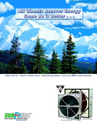
 Ecofresh Rotors/ Wheels are available in a variety of substrates and desiccant coatings.
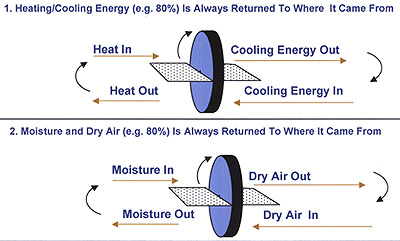
Heat Recovery Wheel Specifications
Rotor/wheel matrix shall be of designed and manufactured for dehumidification and enthalpy recovery at minimum 75% efficiency -
- Wheel Media
a) The substrate: The substrate/ wheel matrix should be only of pure aluminum foil so as to allow.
* quick and efficient uptake of thermal energy.
* sufficient mass for optimum heat transfer
* maximum sensible heat recovery at a relatively low rotational speed of 20 to 25 rpm.
Non metallic substrates made from paper, plastic, synthetic or glass fibre media, will therefore, not be acceptable.
The substrate shall not be made from any material, which is combustible or supports combustion.
b) The Desiccant : The desiccant should be water molecule selective and non-migratory.
The desiccant should be of molecular sieve type, which combines the selectivity of a 3Å molecular sieve desiccant impregnated coating for the 2.8A water molecules, and has the higher diffusivity of the 4Å molecular sieves, so as to ensure the exclusion of contaminants in the air stream, while transferring only water vapour molecules, resulting in selective and fast latent recovery. The performance shall be tested and certified by an accredited laboratory.
The desiccant, of sufficient mass, should be coated with non masking porous binder adhesive on the aluminum substrate so as to allow quick and easy uptake and release of water vapour. A matrix with desiccants impregnated in non metallic substrates, such as synthetic fibre, glass fibre, etc. will not be accepted.
- Rotor : With optimum heat and mass through matrix formed by desiccant, of sufficient mass, coated on an aluminum foil, the rotor should rotate at lower than 20 to 25 RPM, thereby also ensuring long life of belts and reduced wear and tear of seals.
The rotor shall be made of alternate flat and corrugated aluminum foil of uniform width.
The rotor honeycomb matrix foil should be so wound and adhered as to make a structurally very strong and rigid media which shall not get cracked, deformed etc. due to change of temperature or humidity.
The rotor having a diameter upto 2800mm shall have spokes to reinforce the matrix. From 2000mm diameter upwards, the option of a special wing structure, to prevent the rotors from wobbling or deforming due to the successive pressure differentials, will be available.
Sectioned wheels, with pie segments, capable of being assembled in the field, shall be available as an option, above 2000mm in diameter.
The surface of the wheel/rotor should be highly polished to ensure that the vertical run out does not exceed +/- 1mm for every 1 metre diameter, thereby ensuring negligible leakage, if labyrinth non contact seals are provided, and minimal drag, if contact wiper seals are provided.
The radial run out also shall not exceed +/- 1 mm for every 1 meter diameter, thereby minimizing the leakage/drag on the radial seals, and minimize the fluctuation in the tension of the drive belt.
The number of wraps (of alternative corrugated and flat foil) for every inch of rotor radii shall be very consistent to ensure uniform airflow and performance over the entire face in the air stream. Flute height and pitch will be consistent to a very tight tolerance to ensure uniform pressure drop and uniform airflow across the rotor face.
The rotor shall be a non-clogging aluminum media, having a multitude of narrow aluminum foil channels, ensuring a laminar flow, and will allow particles up to 800 microns to pass through it.
d) Cleaning : The media shall be cleanable with compressed air, or low pressure steam or light detergent, without degrading the latent recovery.
2. Performance
The rotor/wheel matrix shall have equal sensible and latent energy recovery.
The weight of desiccant coating and the mass of aluminum foil shall be in a ratio so as to ensure equal recovery of both sensible and latent heat over the operating range. Accordingly, a rotor matrix which has an etched or oxidised surface to make a desiccant on a metal foil and results in insufficient latent recovery and hence unequal recovery, or a rotor matrix made from desiccant integrated in a synthetic fibre matrix which result in insufficient sensible recovery, high rotation speed, and unequal recovery, will not be accepted. The performance shall be tested and certified by an accredited laboratory.
The rotor performance shall be approved by Air-Conditioning and Refrigeration Institute (ARI), USA with ARI standard 1060-2000.
3. Purge Sector
The rotor/wheel should have a field adjustable purge mechanism to provide definite separation of airflow minimising the carryover of bacteria, dust and other pollutants, from the exhaust air to the supply air. It shall be possible, with proper adjustment, to limit cross contamination to less than 0.04% of that of the exhaust air concentration. The performance shall be tested and certified by an accredited laboratory.
4. Wheel Seals
The face and radial seals shall be four (4) pass non-contact labyrinth seals for effective sealing between the two air streams, and also for a minimum wear and tear ensuring infinite life of the seals.
5. The Cassette Frame
The recovery wheel cassette/casing shall be manufactured from tubular structure to provide a self supporting rigid structure, complete with access panels, purge sector, rotor, bearings, seals, drive mechanism complete with belt. The cassette frame and sheet panels will be powder / epoxy coated to prohibit corrosion.
6. Wheel Support System
The wheel media shall be rigidly held by a structural spoke system and shall be supported between two pillow block bearings, which allow maintenance or replacement without the removal of the wheel.
7. Drive System
The wheel must be driven from its perimeter by an adjustable belt system and a constant speed 415v/3ph/50hz motor. Speed reduction shall be by gear motor or through jack shaft and pulleys.